US7311198B2 - Storage device for compact discs - Google Patents
Storage device for compact discs Download PDFInfo
- Publication number
- US7311198B2 US7311198B2 US10/941,368 US94136804A US7311198B2 US 7311198 B2 US7311198 B2 US 7311198B2 US 94136804 A US94136804 A US 94136804A US 7311198 B2 US7311198 B2 US 7311198B2
- Authority
- US
- United States
- Prior art keywords
- compact disc
- opening
- indicia
- lip
- body member
- Prior art date
- Legal status (The legal status is an assumption and is not a legal conclusion. Google has not performed a legal analysis and makes no representation as to the accuracy of the status listed.)
- Expired - Fee Related, expires
Links
Images


Classifications
-
- G—PHYSICS
- G11—INFORMATION STORAGE
- G11B—INFORMATION STORAGE BASED ON RELATIVE MOVEMENT BETWEEN RECORD CARRIER AND TRANSDUCER
- G11B33/00—Constructional parts, details or accessories not provided for in the other groups of this subclass
- G11B33/02—Cabinets; Cases; Stands; Disposition of apparatus therein or thereon
- G11B33/04—Cabinets; Cases; Stands; Disposition of apparatus therein or thereon modified to store record carriers
- G11B33/0405—Cabinets; Cases; Stands; Disposition of apparatus therein or thereon modified to store record carriers for storing discs
- G11B33/0411—Single disc boxes
- G11B33/0422—Single disc boxes for discs without cartridge
Definitions
- This invention relates to a specialty receptacle or package. More particularly, the present invention relates to a device for storing, protecting or displaying compact discs.
- CD compact disc
- a compact disc has digital data on the underside of the CD which are read by a laser mechanism.
- CDs are typically purchased in flattened, hinged cases, commonly referred to as “jewel cases”, although other protective means are sometimes employed.
- the CD is retained in place within a jewel case by a resilient “post” onto which the CD is snapped. It is advisable to avoid touching the underside of the CD, because the data impressed thereon can be made unreadable by skin oils and the like.
- Jewel cases are usually formed of clear transparent plastic which allows a label to be viewed through the walls of the jewel cases.
- jewel cases function well in protecting CD's stored therein, they may not be the best or ideal way for storing or transporting CD's.
- the present invention presents an alternative way for protecting, storing or displaying CD's.
- a device for storing a compact disc includes: (a) a body member having top and bottom surfaces, a portion proximate its perimeter that turns upward so as to allow the member's outer edge to turn back inward towards the center of the member so as to form a lip whose edge defines an opening that lies above the top surface, and (b) indicia projecting downward from the bottom surface, wherein: (i) the lip is formed from a pliable material, (ii) the opening defines a space through which a compact disc can pass with specified friction due to rubbing between the edges of the opening and the compact disc which is to be laid against the member's top surface, (iii) the indicia is located on the bottom surface so as to be within a space defined by the opening of a second, similar device whose top surface is placed below the bottom surface of the first device so that the devices may be stacked one upon the other, and (iv) the upward turned portion proximate the member's perimeter has a height that is greater than
- FIG. 1 is a top view of a preferred embodiment of the present invention showing the general shape of its elements.
- FIG. 2 is a side view of the embodiment shown in FIG. 1 .
- FIG. 3 is a bottom view of the embodiment shown in FIG. 1 .
- FIG. 4 is a bottom view of another embodiment in which the bottom surface has a raised logo or text added to it rather than a generalized geometric pattern as shown in FIG. 3 .
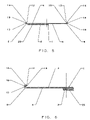
- FIG. 5 is a cross-sectional view taken along the line A-A shown in FIG. 1 .
- FIG. 6 is an enlarged view of the left hand portion of the embodiment shown in FIG. 5 .
- FIG. 7 shows a cross-sectional view similar to that shown in FIG. 5 but in the situation where a number of the embodiments shown in FIG. 5 have been stacked on top of each other.
- FIG. 8 is a perspective view of the embodiment shown in FIG. 1 with a compact disk lying in the device and with a cutaway portion that shows the relation of the disk's edge to the device's lip.
- FIG. 9 is a top view similar to that of FIG. 1 showing the thin, flat protective jacket of the present invention.
- FIG. 10 shows a cross-sectional view along the line 10 - 10 of FIG. 9 .
- FIGS. 1 , 2 and 3 show top, side and bottom views, respectively of a preferred embodiment of the present invention.
- It is a storage and stacking device 1 for either computer, audio or video compact discs.
- It consists of a generally flat body member 2 having top 4 and bottom 6 surfaces.
- Its perimeter 8 has an upward turned portion 10 whose outer edge 12 actually turns back inward so as to form a lip 14 that overhangs and is relatively parallel to the plane defined by the top 4 surface of the body member 2 .
- This lip can also be viewed as defining a circular opening 16 for a plane through which anything must pass in order to make contact with the member's top 4 surface.
- the member's upward turned perimeter portion 10 also serves to form an effective outer, protective wall 18 for any thin, flat object that might be fully lying on the member's top 4 surface.
- This indicia 20 may take the form of any convenient geometric shape, such as the outwardly directed lines shown in FIG. 3 or individual raised surfaces that are judiciously placed at various points on the member's bottom surface 6 .
- a basic purpose of these indicia 20 is to aid in preventing the member's bottom surface 6 from attaching to any wet or otherwise tacky surface on which the member may be laid.
- the indicia 20 of this bottom surface may take the form of a logo, as shown in FIG. 4 , that is used for some type of promotional, novelty or informational purpose (e.g., advertisement, advocacy, sponsorship, endorsement, amusement, material safety data).
- the perimeter of this embodiment of the member 2 takes the form of a circle.
- any other geometrical shape i.e., rectangle, square, polygon
- any other geometrical shape i.e., rectangle, square, polygon
- this device Since this device will be used to store and/or display compact discs, its opening 16 is circular and has a diameter that is slightly less than that of a compact disc. Of course, it should be recognized this opening 16 need not be exactly circular. For example, it could have some type of scalloped edge. What is required of this opening's edge 12 is that it essentially define a space through which a compact disc can pass with some friction due to rubbing between the opening and disc edges and assuming that the lip 14 is pliable.
- the member itself, or at least it's lip 14 is made of elastic material which allows the lip 14 to be bent outward so as to allow a compact disc to pass through the opening 16 and lie on the member's top 4 surface. In this position, the lip 14 is seen to actually overhang and enclose the edges of the compact disc so as to prevent it from falling away from the member's top 4 surface. This is aided by sizing the member's effective outer wall 18 so that it is just greater than the height or thickness of a compact disc so that the lip 14 lies just above a disk lying on the member's top 4 surface. See FIG. 8 which has a cutaway portion that shows the relation of the edge of a compact disc held in the device.
- FIG. 7 shows that there is a relationship between the height of the effective outer wall 18 and the height of the raised indicia 20 that is attached to the member's bottom 6 surface. These heights are established as being approximately equal so as to aid in allowing the devices to be stacked one upon the other in such a manner that the raised indicia fits within the lip's opening 16 and can rest on the member's top 2 surface. This obviously puts a constraint on the places on the member's bottom 6 surface where the raised indicia 20 can be located (i.e., the indicia 20 has to fit through the lip's opening 16 ). Thus, the indicia 20 are located so as to be within a space defined by the opening of a second, similar device whose top surface is placed below the first device's bottom 6 surface.
- More protection for a compact disc can be provided by sizing the height of the effective outer wall 18 so that the gap between the underside of the lip 14 and the member's top surface is sufficiently wide so as to accommodate a thin, flat protective jacket 22 ( FIGS. 9 and 10 ) which is sized similar to a compact disc and lies on the disc's top surface when it is placed in the device.
- the jacket 22 has an outer periphery 24 captured under the lip 14 ( FIG. 10 ).
Abstract
A device for storing a compact disc includes: (a) a body member (2) having a top (4) and bottom (6) surfaces, a portion proximate its perimeter that turns upward so as to allow the member's outer edge (12) to turn back inward towards the center of the member so as to form a lip (14) whose edge (12) defines an opening (16) that lies above the top (4) surface, and (b) indicia (20) projecting downward from the bottom (6) surface, wherein: (i) the lip (14) is formed from a pliable material, (ii) the opening defines a space through which a compact disc can pass with specified friction due to rubbing between the edges of the opening (12) and the compact disc which is to be laid against the member's top surface (4), (iii) the indicia (20) is located on the bottom (6) surface so as to be within a space defined by the opening of a second, similar device whose top surface is placed below the bottom (6) surface so that the devices may be stacked one upon the other, and (iv) the upward turned portion proximate the member's perimeter has a height that is greater than the thickness of the compact disc.
Description
1. Field of the Invention
This invention relates to a specialty receptacle or package. More particularly, the present invention relates to a device for storing, protecting or displaying compact discs.
2. Description of Prior Art
Currently the compact disc or CD is the medium of choice for a wide range of electronic media, e.g., recorded music and video as well as computer software. A compact disc has digital data on the underside of the CD which are read by a laser mechanism.
CD's are typically purchased in flattened, hinged cases, commonly referred to as “jewel cases”, although other protective means are sometimes employed. The CD is retained in place within a jewel case by a resilient “post” onto which the CD is snapped. It is advisable to avoid touching the underside of the CD, because the data impressed thereon can be made unreadable by skin oils and the like. Jewel cases are usually formed of clear transparent plastic which allows a label to be viewed through the walls of the jewel cases.
There are a number of types of structures or racks for holding a plurality of CD's at a location convenient to a CD player or deck. Some types have slots sized to allow a CD within a jewel case to be placed therein.
Although jewel cases function well in protecting CD's stored therein, they may not be the best or ideal way for storing or transporting CD's. The present invention presents an alternative way for protecting, storing or displaying CD's.
There has been summarized above, rather broadly, the background that is related to the present invention in order that the context of the present invention may be better understood and appreciated. In this regard, it is instructive to also consider the objects and advantages of the present invention.
It is an object of the present invention to provide a storage device for computer, audio and video compact discs.
It is another object of the present invention to provide promotional device for use with computer, audio and video compact discs.
It is also an object of the present invention to provide a storage device for computer, audio and video compact discs which also has value as a promotional tool because of the ability to place promotional indicia on the especially crafted lower surface of the device.
It is an additional object of the present invention to provide a protective device for computer, audio and video compact discs.
It is an object of the present invention to provide a means for extending the service life of computer, audio and video compact discs.
It is another object of the present invention to provide a means for storing and stacking both individual and groups of computer, audio and video compact discs.
These and other objects and advantages of the present invention will become readily apparent as the invention is better understood by reference to the accompanying summary, drawings and the detailed description that follows.
In a first preferred embodiment, a device for storing a compact disc includes: (a) a body member having top and bottom surfaces, a portion proximate its perimeter that turns upward so as to allow the member's outer edge to turn back inward towards the center of the member so as to form a lip whose edge defines an opening that lies above the top surface, and (b) indicia projecting downward from the bottom surface, wherein: (i) the lip is formed from a pliable material, (ii) the opening defines a space through which a compact disc can pass with specified friction due to rubbing between the edges of the opening and the compact disc which is to be laid against the member's top surface, (iii) the indicia is located on the bottom surface so as to be within a space defined by the opening of a second, similar device whose top surface is placed below the bottom surface of the first device so that the devices may be stacked one upon the other, and (iv) the upward turned portion proximate the member's perimeter has a height that is greater than the thickness of the compact disc.
Thus, there has been summarized above, rather broadly, the present invention in order that the detailed description that follows may be better understood and appreciated. There are, of course, additional features of the invention that will be described hereinafter and which will form the subject matter of any eventual claims to this invention.
Before explaining at least one embodiment of the present invention in detail, it is to be understood that the invention is not limited in its application to the details of construction and to the arrangements of the components set forth in the following description or illustrated in the drawings. The invention is capable of other embodiments and of being practiced and carried out in various ways. Also, it is to be understood that the phraseology and terminology employed herein are for the purpose of description and should not be regarded as limiting.
Attached to or molded into and projecting downward from the member's bottom 6 surface is raised indicia 20. This indicia 20 may take the form of any convenient geometric shape, such as the outwardly directed lines shown in FIG. 3 or individual raised surfaces that are judiciously placed at various points on the member's bottom surface 6. A basic purpose of these indicia 20 is to aid in preventing the member's bottom surface 6 from attaching to any wet or otherwise tacky surface on which the member may be laid. Alternatively, the indicia 20 of this bottom surface may take the form of a logo, as shown in FIG. 4 , that is used for some type of promotional, novelty or informational purpose (e.g., advertisement, advocacy, sponsorship, endorsement, amusement, material safety data).
As shown in FIGS. 5 and 6 , the perimeter of this embodiment of the member 2 takes the form of a circle. However, any other geometrical shape (i.e., rectangle, square, polygon) could be used.
Since this device will be used to store and/or display compact discs, its opening 16 is circular and has a diameter that is slightly less than that of a compact disc. Of course, it should be recognized this opening 16 need not be exactly circular. For example, it could have some type of scalloped edge. What is required of this opening's edge 12 is that it essentially define a space through which a compact disc can pass with some friction due to rubbing between the opening and disc edges and assuming that the lip 14 is pliable.
The member itself, or at least it's lip 14, is made of elastic material which allows the lip 14 to be bent outward so as to allow a compact disc to pass through the opening 16 and lie on the member's top 4 surface. In this position, the lip 14 is seen to actually overhang and enclose the edges of the compact disc so as to prevent it from falling away from the member's top 4 surface. This is aided by sizing the member's effective outer wall 18 so that it is just greater than the height or thickness of a compact disc so that the lip 14 lies just above a disk lying on the member's top 4 surface. See FIG. 8 which has a cutaway portion that shows the relation of the edge of a compact disc held in the device.
More protection for a compact disc can be provided by sizing the height of the effective outer wall 18 so that the gap between the underside of the lip 14 and the member's top surface is sufficiently wide so as to accommodate a thin, flat protective jacket 22 (FIGS. 9 and 10 ) which is sized similar to a compact disc and lies on the disc's top surface when it is placed in the device. The jacket 22 has an outer periphery 24 captured under the lip 14 (FIG. 10 ).
Although the foregoing disclosure relates to preferred embodiments of the invention, it is understood that these details have been given for the purposes of clarification only. Various changes and modifications of the invention will be apparent, to one having ordinary skill in the art, without departing from the spirit and scope of the invention.
Claims (3)
1. A device for storing a compact disc comprising:
a body member (2) having a top surface (4) and a bottom (6) surface, and a portion proximate a perimeter of said body member that turns upward so as to allow an outer edge (18) of said body member to turn back inward toward a center of said body member so as to form a lip (14) whose inner edge (12) defines an opening (16) that lies above said top (4) surface, said lip having an upper surface,
indicia (20) projecting downward from said bottom (6) surface,
wherein said lip (14) is formed from a pliable material, and
wherein said opening configured so as to allow a compact disc to pass through said opening, with specified friction due to rubbing between the edges of the opening (12) and said compact disc, so that said compact disc may lay against said member top surface (4), said indicia (20) being located on said bottom (6) surface spaced radially inwardly from said outer edge of said body member so as to be within a space defined by an opening of a second, similar device whose top surface is placed below said bottom (6) surface so that said devices may be stacked one upon the other with said indicia entering said opening of said second, similar device, and a thin flat jacket (22) that is configured to sit on and cover a top said surface of a compact disc and fit through said opening (16) when a said compact disc has been placed in said device.
2. A device as recited in claim 1 , wherein said upward turned portion proximate the perimeter of said member (2) has a height that is greater than a thickness of a compact disc adapted to be placed into said device.
3. A device as recited in claim 1 , wherein said indicia are configured to communicate a message that is used for a purpose selected from the group consisting of promotional, novelty or informational purposes.
Priority Applications (2)
| Application Number | Priority Date | Filing Date | Title |
|---|---|---|---|
| US10/941,368 US7311198B2 (en) | 2004-09-15 | 2004-09-15 | Storage device for compact discs |
| US11/384,119 US20060185324A1 (en) | 2004-09-15 | 2006-03-20 | Storage device for compact discs |
Applications Claiming Priority (1)
| Application Number | Priority Date | Filing Date | Title |
|---|---|---|---|
| US10/941,368 US7311198B2 (en) | 2004-09-15 | 2004-09-15 | Storage device for compact discs |
Related Child Applications (1)
| Application Number | Title | Priority Date | Filing Date |
|---|---|---|---|
| US11/384,119 Division US20060185324A1 (en) | 2004-09-15 | 2006-03-20 | Storage device for compact discs |
Publications (2)
| Publication Number | Publication Date |
|---|---|
| US20050016878A1 US20050016878A1 (en) | 2005-01-27 |
| US7311198B2 true US7311198B2 (en) | 2007-12-25 |
Family
ID=34080973
Family Applications (2)
| Application Number | Title | Priority Date | Filing Date |
|---|---|---|---|
| US10/941,368 Expired - Fee Related US7311198B2 (en) | 2004-09-15 | 2004-09-15 | Storage device for compact discs |
| US11/384,119 Abandoned US20060185324A1 (en) | 2004-09-15 | 2006-03-20 | Storage device for compact discs |
Family Applications After (1)
| Application Number | Title | Priority Date | Filing Date |
|---|---|---|---|
| US11/384,119 Abandoned US20060185324A1 (en) | 2004-09-15 | 2006-03-20 | Storage device for compact discs |
Country Status (1)
| Country | Link |
|---|---|
| US (2) | US7311198B2 (en) |
Cited By (2)
| Publication number | Priority date | Publication date | Assignee | Title |
|---|---|---|---|---|
| US20090260025A1 (en) * | 2008-04-11 | 2009-10-15 | Wayne Chertoff | Optical disc receptacle |
| US20140262872A1 (en) * | 2013-03-14 | 2014-09-18 | Sonoco Development, Inc. | Disk retaining package |
Families Citing this family (2)
| Publication number | Priority date | Publication date | Assignee | Title |
|---|---|---|---|---|
| US7409698B2 (en) * | 2005-10-15 | 2008-08-05 | Mark Tjensvold | Optical disc case usable in player with disc encased therein |
| US8469187B2 (en) * | 2011-01-19 | 2013-06-25 | Joseph Clay Wattenbarger | Watertight stretch covering skin for smokeless tobacco cans |
Citations (17)
| Publication number | Priority date | Publication date | Assignee | Title |
|---|---|---|---|---|
| USD357388S (en) | 1990-09-27 | 1995-04-18 | Kate Gaffin | Coaster |
| US5495953A (en) | 1993-03-08 | 1996-03-05 | Bearth; Urs | Device for storing compact discs and the like |
| US5775659A (en) | 1997-06-12 | 1998-07-07 | Hartlaub; Thaddeus J. | Compact disk drink coaster |
| US6077583A (en) * | 1998-03-03 | 2000-06-20 | Park; Arnold | Digital information guard |
| US6112917A (en) | 1998-11-23 | 2000-09-05 | Denstor Mobile Storage Systems, Inc. | Moveable file storage supporting apparatus |
| US6179121B1 (en) | 1998-08-05 | 2001-01-30 | Speculative Incorporated | Device for transport and splayed display of media |
| US6188032B1 (en) | 1999-10-06 | 2001-02-13 | Erick V. Hartman | Stacking, self-cleaning CD holder |
| USD460899S1 (en) | 2000-04-17 | 2002-07-30 | Pollyflame International B.V. | Coaster |
| US20030131513A1 (en) * | 2001-12-17 | 2003-07-17 | Runge Mark Fritz | Elastically and monolithically marginated display device |
| US6619608B1 (en) | 2002-04-25 | 2003-09-16 | Menasha Corporation | Promotional coaster |
| US6705472B2 (en) | 1999-05-07 | 2004-03-16 | David Webster Cross | CD storage system |
| US6771588B2 (en) * | 2002-07-01 | 2004-08-03 | D- | Protective cover for optically read digital disks |
| US6817025B2 (en) * | 2001-02-22 | 2004-11-09 | Gregg M. Boorman | Nesting optical disc holder |
| US6860388B2 (en) * | 2002-09-20 | 2005-03-01 | Gregg M. Boorman | Optical disc holder |
| US6883663B2 (en) * | 2003-03-11 | 2005-04-26 | Steven Laut | Stretchable media disk packaging |
| US6901600B2 (en) * | 2002-01-03 | 2005-05-31 | Julian Liu | Protective cover for a data storage disc and method of use |
| US6964401B1 (en) * | 2004-06-21 | 2005-11-15 | Michael Sean Kelley | Promotional item and advertising method |
Family Cites Families (4)
| Publication number | Priority date | Publication date | Assignee | Title |
|---|---|---|---|---|
| JP2970183B2 (en) * | 1992-03-03 | 1999-11-02 | 松下電器産業株式会社 | Wafer transfer and storage method and wafer carrier |
| US5690220A (en) * | 1996-10-16 | 1997-11-25 | Swan; Raleigh | Packaging arrangement for display and storage of compact disks |
| JP3951422B2 (en) * | 1998-03-23 | 2007-08-01 | トヨタ自動車株式会社 | Exhaust purification device for multi-cylinder internal combustion engine |
| US7089712B2 (en) * | 2004-05-18 | 2006-08-15 | The Form House, Inc. | Apparatus and method for producing a DVD carrier assembly |
-
2004
- 2004-09-15 US US10/941,368 patent/US7311198B2/en not_active Expired - Fee Related
-
2006
- 2006-03-20 US US11/384,119 patent/US20060185324A1/en not_active Abandoned
Patent Citations (17)
| Publication number | Priority date | Publication date | Assignee | Title |
|---|---|---|---|---|
| USD357388S (en) | 1990-09-27 | 1995-04-18 | Kate Gaffin | Coaster |
| US5495953A (en) | 1993-03-08 | 1996-03-05 | Bearth; Urs | Device for storing compact discs and the like |
| US5775659A (en) | 1997-06-12 | 1998-07-07 | Hartlaub; Thaddeus J. | Compact disk drink coaster |
| US6077583A (en) * | 1998-03-03 | 2000-06-20 | Park; Arnold | Digital information guard |
| US6179121B1 (en) | 1998-08-05 | 2001-01-30 | Speculative Incorporated | Device for transport and splayed display of media |
| US6112917A (en) | 1998-11-23 | 2000-09-05 | Denstor Mobile Storage Systems, Inc. | Moveable file storage supporting apparatus |
| US6705472B2 (en) | 1999-05-07 | 2004-03-16 | David Webster Cross | CD storage system |
| US6188032B1 (en) | 1999-10-06 | 2001-02-13 | Erick V. Hartman | Stacking, self-cleaning CD holder |
| USD460899S1 (en) | 2000-04-17 | 2002-07-30 | Pollyflame International B.V. | Coaster |
| US6817025B2 (en) * | 2001-02-22 | 2004-11-09 | Gregg M. Boorman | Nesting optical disc holder |
| US20030131513A1 (en) * | 2001-12-17 | 2003-07-17 | Runge Mark Fritz | Elastically and monolithically marginated display device |
| US6901600B2 (en) * | 2002-01-03 | 2005-05-31 | Julian Liu | Protective cover for a data storage disc and method of use |
| US6619608B1 (en) | 2002-04-25 | 2003-09-16 | Menasha Corporation | Promotional coaster |
| US6771588B2 (en) * | 2002-07-01 | 2004-08-03 | D- | Protective cover for optically read digital disks |
| US6860388B2 (en) * | 2002-09-20 | 2005-03-01 | Gregg M. Boorman | Optical disc holder |
| US6883663B2 (en) * | 2003-03-11 | 2005-04-26 | Steven Laut | Stretchable media disk packaging |
| US6964401B1 (en) * | 2004-06-21 | 2005-11-15 | Michael Sean Kelley | Promotional item and advertising method |
Cited By (3)
| Publication number | Priority date | Publication date | Assignee | Title |
|---|---|---|---|---|
| US20090260025A1 (en) * | 2008-04-11 | 2009-10-15 | Wayne Chertoff | Optical disc receptacle |
| US7665277B2 (en) * | 2008-04-11 | 2010-02-23 | Wayne Chertoff | Optical disc receptacle |
| US20140262872A1 (en) * | 2013-03-14 | 2014-09-18 | Sonoco Development, Inc. | Disk retaining package |
Also Published As
| Publication number | Publication date |
|---|---|
| US20060185324A1 (en) | 2006-08-24 |
| US20050016878A1 (en) | 2005-01-27 |
Similar Documents
| Publication | Publication Date | Title |
|---|---|---|
| US6123192A (en) | Rosette with release tab for holding disc shaped elements | |
| US7409698B2 (en) | Optical disc case usable in player with disc encased therein | |
| US5896986A (en) | Rosette having radially deflectable finger ends for holding disc shaped elements | |
| ES2125054T5 (en) | DEVICE FOR RETAINING A COMPACT DISC. | |
| US5417324A (en) | Clear molded thermoplastic compact disc supporting tray | |
| US5727680A (en) | Impact resistant compact disc tray structure | |
| US20070075080A1 (en) | Beverage Container Lids With Combined Display Area And Cooling/Insulating Structure | |
| US6041946A (en) | Compact disc holder | |
| RU2335812C1 (en) | Container for digital disks storing upon tilt | |
| US20060185324A1 (en) | Storage device for compact discs | |
| US6749061B2 (en) | Compact disc carrying container | |
| US4232461A (en) | Phonograph record album index tabs | |
| WO2005013247A1 (en) | Promotional compact disc carrier system | |
| EP0554242A1 (en) | Optical storage disc protector | |
| US6307830B1 (en) | Protected recording medium | |
| US6651811B2 (en) | Anti-pilferage device for optical disc holder | |
| US7708139B2 (en) | Recording medium storage package having improved rosette | |
| US5906276A (en) | Storage tray for holding disc shaped elements | |
| CA2208807A1 (en) | A cd sheath | |
| EP2280395A1 (en) | Protective cover for disk-like recording medium | |
| CA2350312C (en) | Rosette having radially deflectable finger ends for holding disc shaped elements | |
| EP1276115A2 (en) | Holder for compact discs | |
| KR200357617Y1 (en) | Tray for compact disk case | |
| US20030075461A1 (en) | Carriers for compact discs | |
| US20170178694A1 (en) | Electronic media disc storage tray component |
Legal Events
| Date | Code | Title | Description |
|---|---|---|---|
| REMI | Maintenance fee reminder mailed | ||
| LAPS | Lapse for failure to pay maintenance fees | ||
| STCH | Information on status: patent discontinuation |
Free format text: PATENT EXPIRED DUE TO NONPAYMENT OF MAINTENANCE FEES UNDER 37 CFR 1.362 |
|
| FP | Lapsed due to failure to pay maintenance fee |
Effective date: 20111225 |